 Full Fan-out Transceiver Test Systems for Radio Testing
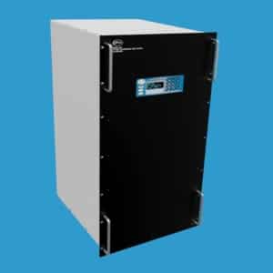
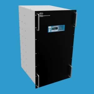
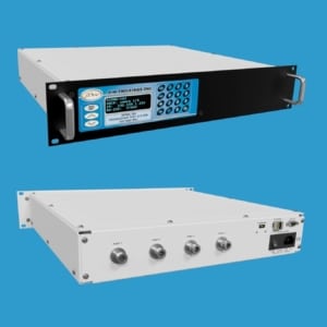
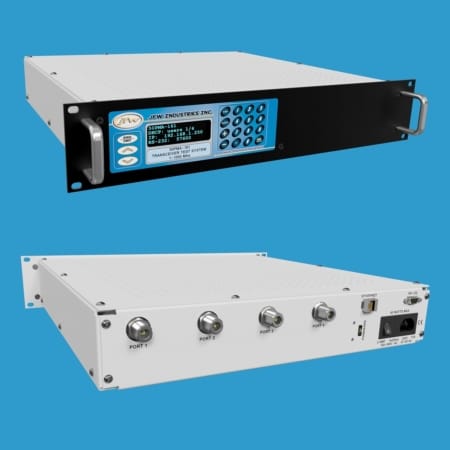
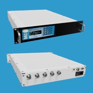
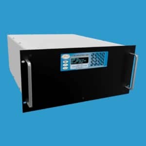
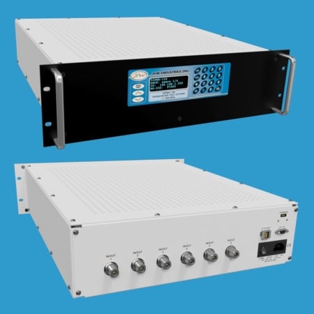
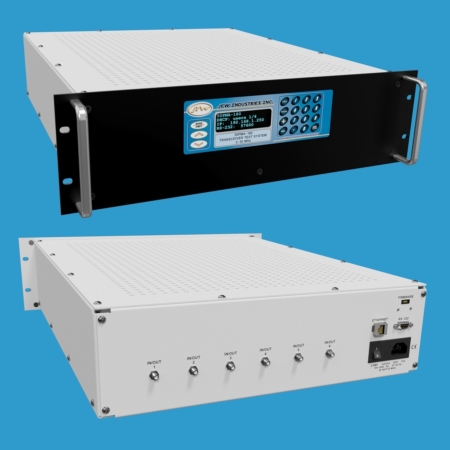
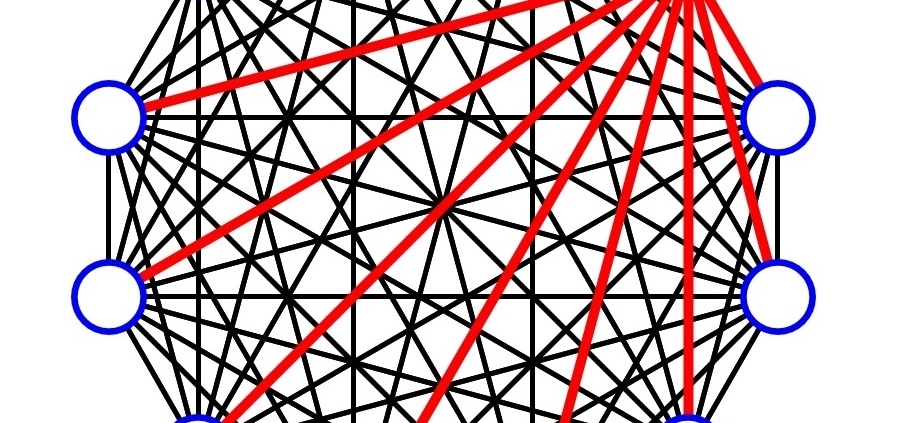
A full fan-out transceiver test system is constructed as a fully meshed matrix. There is a path between every pair of ports. Every path has its own individually controlled programmable attenuator. This construction is ideal for testing radio-to-radio communication because every path can be set to a unique dB setting. The main cost driver for this design is the number of individually controlled attenuators. The number of attenuators increase as the number of ports increase.
6 Port Design: 6 fully meshed ports with 15 paths and 15 attenuators
8 Port Design: 8 fully meshed ports with 28 paths and 28 attenuators
12 Port Design: 12 fully meshed ports with 66 paths and 66 attenuators
16 Port Design: 16 fully meshed ports with 120 paths and 120 attenuators
32 Port Design: 32 fully meshed ports with 496 paths and 496 attenuators
Each path through the matrix has its own individually controlled programmable attenuator. The programmable attenuators allow the transmission from one port to be received at all other ports at different signal levels. This allows the simulation of a network where each device has a different distance (i.e. attenuation setting) from all other devices. The attenuators can be remotely controlled to simulate static or dynamic environments.
If you do not find a model that meets your requirements, please contact JFW for assistance or use our Inquiry Form. JFW does not charge NREs for new test system models.
| JFW Model # | Impedance | Configuration | dB Total | dB Step | Frequency Start | Frequency Stop | Control | RF Connectors |
|---|---|---|---|---|---|---|---|---|
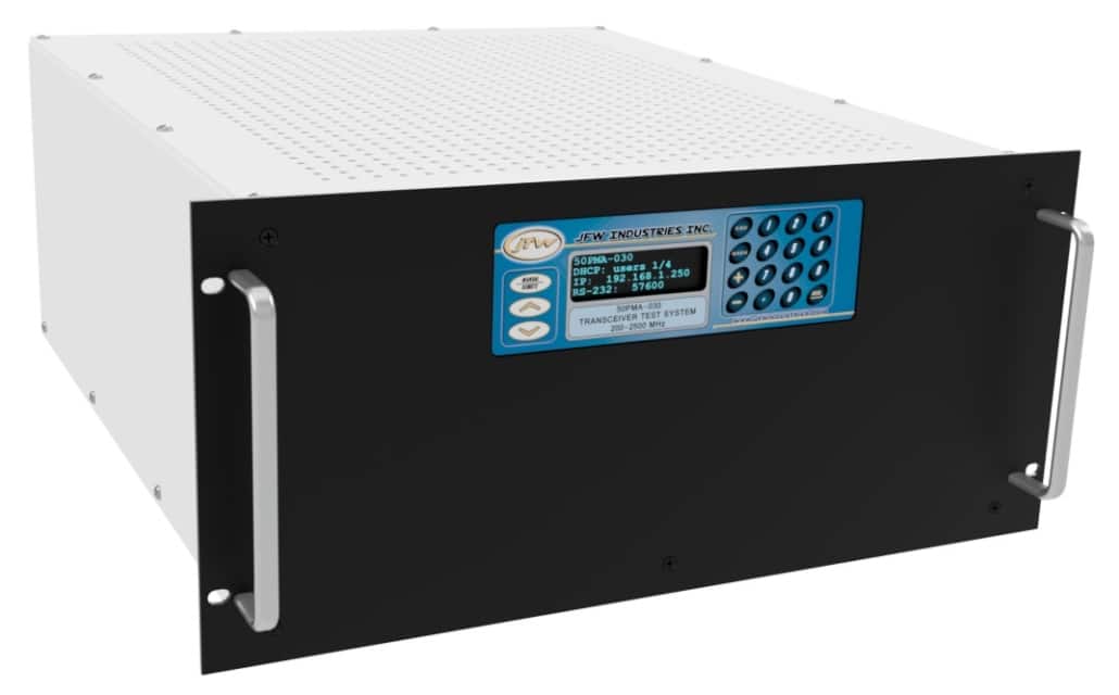
| 50PMA-030 | 50 Ohm | 8 Ports | 127 dB | 1 dB | 200 MHz | 2500 MHz | Keypad, Ethernet, RS-232 | SMA |
| 50PMA-036 | 50 Ohm | 8 Ports | 95 dB | 1 dB | 500 MHz | 6000 MHz | Keypad, Ethernet, RS-232 | N, SMA |
| 50PMA-041 | 50 Ohm | 32 Ports | 63 dB | 1 dB | 30 MHz | 3000 MHz | Keypad, Ethernet, RS-232 | N, SMA, TNC |
| 50PMA-044 | 50 Ohm | 8 Ports | 95 dB | 1 dB | 30 MHz | 3000 MHz | Keypad, Ethernet, RS-232 | N, SMA, TNC |
| 50PMA-055 | 50 Ohm | 16 Ports | 95 dB | 1 dB | 30 MHz | 3000 MHz | Keypad, Ethernet, RS-232 | N, SMA, TNC |
| 50PMA-069 | 50 Ohm | 12 Ports | 95 dB | 1 dB | 30 MHz | 3000 MHz | Keypad, Ethernet, RS-232 | N, SMA, TNC |
| 50PMA-070 | 50 Ohm | 16 Ports | 95 dB | 1 dB | 2000 MHz | 6000 MHz | Keypad, Ethernet, RS-232 | N, SMA |
| 50PMA-072 | 50 Ohm | 4 Ports | 95 dB | 1 dB | 30 MHz | 3000 MHz | Keypad, Ethernet, RS-232 | N, SMA |
| 50PMA-074 | 50 Ohm | 6 Ports | 95 dB | 1 dB | 30 MHz | 3000 MHz | Keypad, Ethernet, RS-232 | N, SMA |
| 50PMA-075 | 50 Ohm | 6 Ports | 95 dB | 1 dB | 2000 MHz | 6000 MHz | Keypad, Ethernet, RS-232 | N, SMA |
| 50PMA-076 | 50 Ohm | 8 Ports | 95 dB | 1 dB | 2000 MHz | 6000 MHz | Keypad, Ethernet, RS-232 | SMA |
| 50PMA-080 | 50 Ohm | 6 Ports | 95 dB | 1 dB | 500 MHz | 6000 MHz | Keypad, Ethernet, RS-232 | N, SMA, TNC |
| 50PMA-081 | 50 Ohm | 9 Ports | 95 dB | 1 dB | 500 MHz | 6000 MHz | Keypad, Ethernet, RS-232 | N, SMA |
| 50PMA-083 | 50 Ohm | 4 Ports | 95 dB | 1 dB | 500 MHz | 6000 MHz | Keypad, Ethernet, RS-232 | N, SMA |
| 50PMA-092 | 50 Ohm | 9 Ports | 95 dB | 1 dB | 30 MHz | 3000 MHz | Keypad, Ethernet, RS-232 | N, SMA, TNC |
| 50PMA-098 | 50 Ohm | 5 Ports | 95 dB | 1 dB | 2000 MHz | 6000 MHz | Keypad, Ethernet, RS-232 | N, SMA, TNC |
| 50PMA-106 | 50 Ohm | 4 Ports | 95 dB | 1 dB | 2000 MHz | 6000 MHz | Keypad, Ethernet, RS-232 | N, SMA, TNC |
| 50PMA-114 | 50 Ohm | 5 Ports | 95 dB | 1 dB | 30 MHz | 3000 MHz | Keypad, Ethernet, RS-232 | N, SMA, TNC |
| 50PMA-151 | 50 Ohm | 8 Ports | 63 dB | 1 dB | 2000 MHz | 8000 MHz | Keypad, Ethernet, RS-232 | N, SMA |
| 50PMA-155 | 50 Ohm | 12 Ports | 95 dB | 1 dB | 350 MHz | 6000 MHz | Keypad, Ethernet, RS-232 | N, SMA |
| 50PMA-179 | 50 Ohm | 4 Ports | 95 dB | 1 dB | 2 MHz | 30 MHz | Keypad, Ethernet, RS-232 | N, SMA |
| 50PMA-161 | 50 Ohm | 4 Ports | 95 dB | 1 dB | 1 MHz | 1000 MHz | Keypad, Ethernet, RS-232 | N, SMA |
| 50PMA-164 | 50 Ohm | 6 Ports | 95 dB | 1 dB | 1 MHz | 1000 MHz | Keypad, Ethernet, RS-232 | N, SMA |
| 50PMA-180 | 50 Ohm | 6 Ports | 95 dB | 1 dB | 2 MHz | 30 MHz | Keypad, Ethernet, RS-232 | N, SMA, TNC |
| 50PMA-181 | 50 Ohm | 8 Ports | 95 dB | 1 dB | 2 MHz | 30 MHz | Keypad, Ethernet, RS-232 | N, SMA, TNC |
4 Port Full Fan-out Transceiver Test System Example
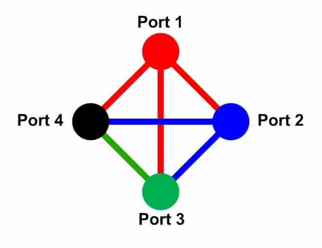
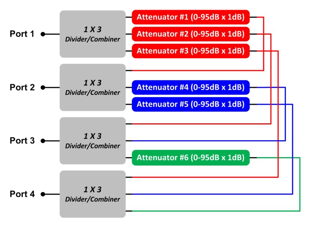
Below are two diagrams. The left diagram shows how all ports are connected to each other. The right diagram shows the attenuator addressing for each path. A full fan-out 4 port transceiver test system requires a total of 6 programmable attenuators. Each of the programmable attenuators can be individually controlled. The full fan-out configuration allows for each path to be set to its own unique attenuation setting. A radio connected to port #1 can transmit a signal to radios on ports #2, 3, 4 at different signal levels simultaneously. Our latest generation firmware allows for the attenuators to be faded individually or grouped together and faded as a group.
Custom Models
The models listed in the above table showcase some of our standard transceiver test systems. However, most of JFW’s test system business involves custom designed models. JFW does not charge NREs for custom models. We encourage you to email us your specific requirement at sales@jfwindustries.com. We will respond with a ROM (rough order of magnitude) quote in 1-2 days.
Remote Commands
The transceiver test system models are available with Ethernet/Serial remote control. Our current generation of Ethernet/Serial firmware is called 3.x.x firmware. It features easy to use ASCII formatted remote commands. Use our Ethernet Test Box to demo the 3.x.x firmware.
Test Software
JFW provides a GUI test program with all Ethernet and RS-232 controlled test systems. The test software for transceiver test systems has all of the remote commands built in for easy testing. In addition to the remote commands, the GUI test program has additional functionality such as keypress, handover, and indefinite handover. Several of our sample test programs are available online.
- Display 15 Products per page

 Full Fan-out Transceiver Test Systems for Radio Testing