Custom RF Test Systems
A large portion of test systems that JFW manufactures are custom RF test systems that we do not list on the website. JFW will integrate our own RF components (i.e. step attenuators, RF switches, power dividers) and non-JFW RF components (i.e. filters, isolators) into a remotely controlled RF sub system to your specifications. We do not charge NRE’s (non-recurring engineering fees) for new model numbers. Please email a block diagram or description to our engineering team and we will generate a quote for your custom RF test system.
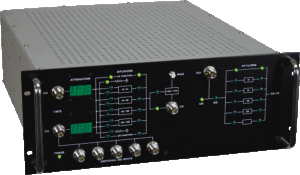
Block Diagram Panel Block Diagram on Front Panel w/LED Indicators
This custom RF test system contains programmable attenuators and RF switches. The current dB setting of the attenuators is displayed on the front panel. All switch settings are shown via LED’s that are integrated to be part of the block diagram that is screened on the front panel.
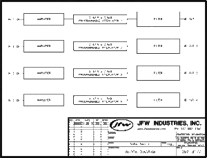
Non-JFW Components
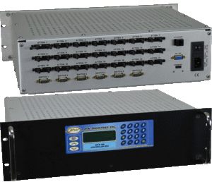
This custom RF test system model contains programmable attenuators, amplifiers and filters. The only components in this system that are JFW built are the step attenuators. The customer specified the amplifiers and filters. We integrated all of the RF components into a single rack mount chassis with Ethernet/RS-232 control.
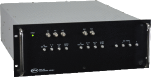
Custom Labeling & RF Connector Placement
This test systems contains directional couplers, programmable attenuators, diplexers, reactive power divider/combiners and fixed pads. The parts are configured per the customer block diagram. All RF connectors are on the front panel with custom labeling per customer request.
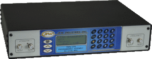
Custom Hardwired Attenuator Blocks
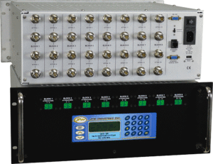
This programmable attenuator assembly contains 16 attenuators. The customer needed the attenuators hardwired as pairs. Also, the current dB setting of the 8 blocks had to be displayed on the front panel. If you click the picture it will enlarge and you will see the assigned block #’s and attenuators #’s. All N female connectors are located on the rear panel. Block dB settings and keypad located on the front panel.
Custom Labeling & RF Connector Placement
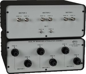
This model is a manually controlled limited configuration handover test system. The rotary knobs on the front panel allow the attenuation to be manually adjusted. This unit has TNC female and SMA female connectors. Placement and labeling of the RF connectors is per customer request
